IVF visual flow indicators
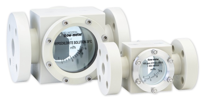
The visual flow indicators type IVF are suitable for instantaneous control of liquids for all industrial processes. They assure an instantaneous indication of the range in horizontal pipelines using a paddle or a pointer with magnetic gear. When a paddle is used, the scale can be read on a graduated glass window, while for indicators with pointer, the scale is read on an external dial. These indicators can also be used for free passage, just to control the fluid passing.
Other features, besides the ones already mentioned, are:
- different kinds of construction material depending on fluids to be controlled;
- construction with threaded or flanged connections.
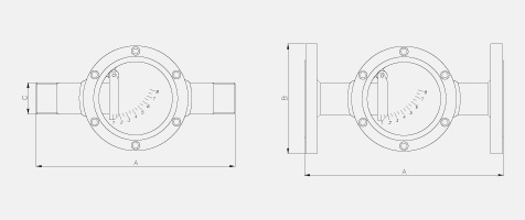
Technical Specifications (below)
Threaded connections
Flanged connections
Tech Info
|
FEATURES |
|
|
Accuracy |
± 10% V.F.S. |
|
Working max. pressure |
metal body: see table |
|
Working max. temperature |
metal body: 120° C. |
|
ACCESSORIES |
|
Silicone or P.T.F.E. gaskets |
|
Pointer range indication with external magnetic gear |
|
TYPE |
WATER Maximum flow m3/h |
A |
FLANGE B |
THREAD C |
GLASS Ø |
MAX WORKING PRESS. |
|
|
UNI PN 10/16 |
ANSI 150 LB |
||||||
|
IVF 15 |
2 |
170 |
DN 15 |
1/2” |
1/2" |
60 |
10 |
|
IVF 20 |
3 |
180 |
DN 20 |
3/4" |
3/4" |
60 |
10 |
|
IVF 25 |
5 |
190 |
DN 25 |
1" |
1" |
70 |
10 |
|
IVF 32 |
8 |
220 |
DN 32 |
1" 1/4 |
1" 1/4" |
100 |
10 |
|
IVF 40 |
12 |
260 |
DN 40 |
1" 1/2 |
1" 1/2" |
120 |
10 |
|
IVF 50 |
20 |
280 |
DN 50 |
2" |
2" |
120 |
10 |
|
IVF 65 |
40 |
300 |
DN 65 |
2" 1/2" |
2" 1/2 |
145 |
8 |
|
IVF 80 |
60 |
330 |
DN 80 |
3" |
3" |
180 |
8 |
|
IVF 100 |
150 |
400 |
DN 100 |
4" |
4" |
210 |
8 |

Download Area
Products Visual Flow Indicators
visual flow indicators

